Working with complex CAD models in COMSOL Multiphysics

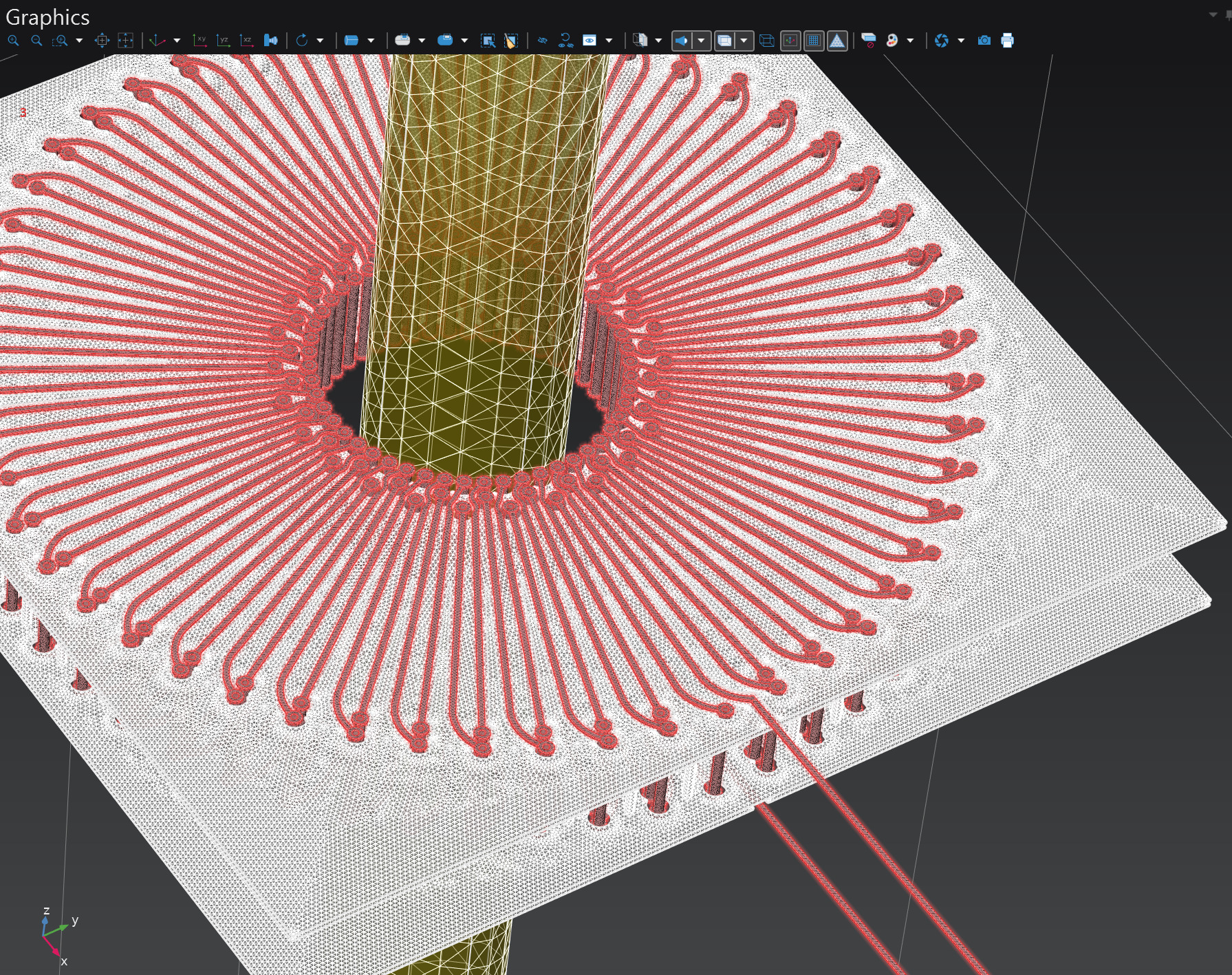
Once upon a time, there was a STEP model of a PCB planar transformer exported from KiCAD and imported into COMSOL for its evaluation as part of a 3D AC magnetic fields problem. The coil came in two revisions, the first revision having a simpler geometry compared to the second one. Due to some unknowable peculiarities of the KiCAD v9 STEP export feature, the two models were exported slightly differently despite using the exact same output settings:
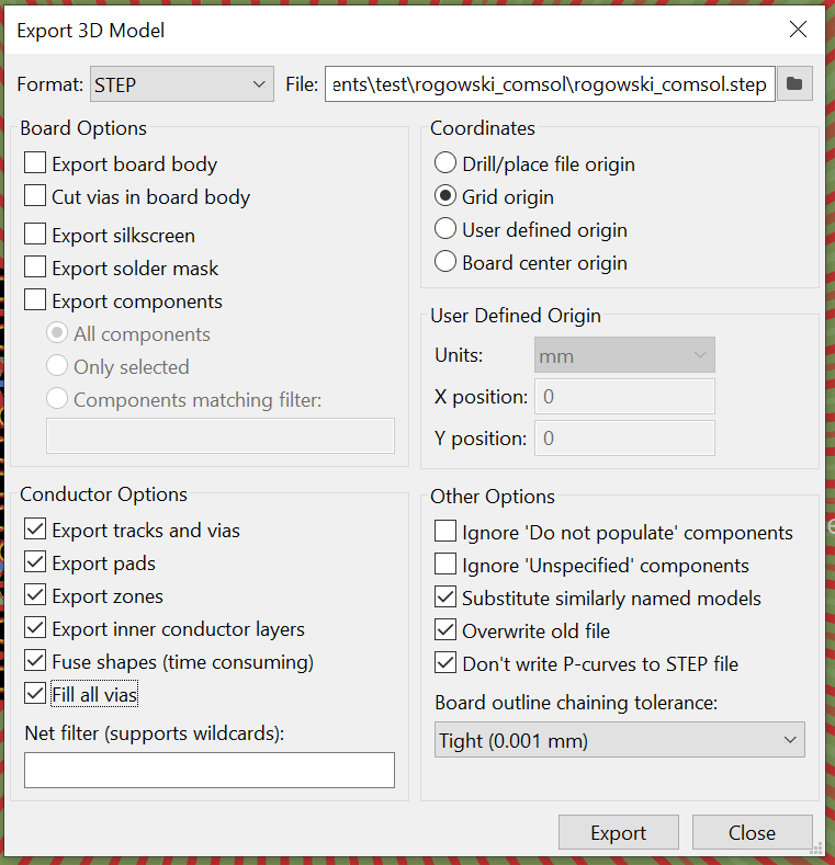
The differences were minor enough that one wouldn’t notice them just by spinning the model in the COMSOL model builder view or a CAD. However, soon it was discovered that while the first model could be successfully simulated in COMSOL using pretty much default settings aside from a slight mesh refinement (taking about 4 days and ~190 GiB of RAM with the GMRES solver), the second one was consistently failing to converge. The first sign of trouble was that the mesh builder was reporting warnings related to small mesh elements. My first solution was to tweak the minimum element size setting to try and better resolve finer regions of the model, but soon I discovered that the issue is that the second model contained poorly resolved artifacts that weren’t present in the original one. Consider this screenshot taken in SolidWorks, notice the small region near the center:
The size of the edge near the marker is around one micron. The original KiCAD layout does not really call for a copper thickness change in this region, and it is only present in the second model, so strictly speaking KiCAD is at fault for generating phantom geometry, but nevertheless we are the ones who are to deal with it.
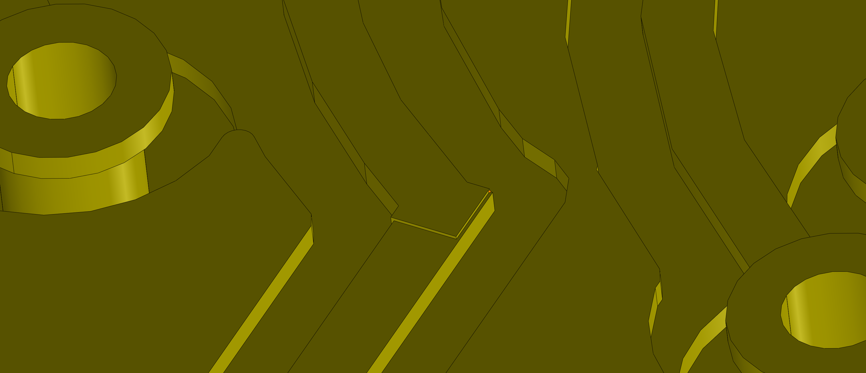
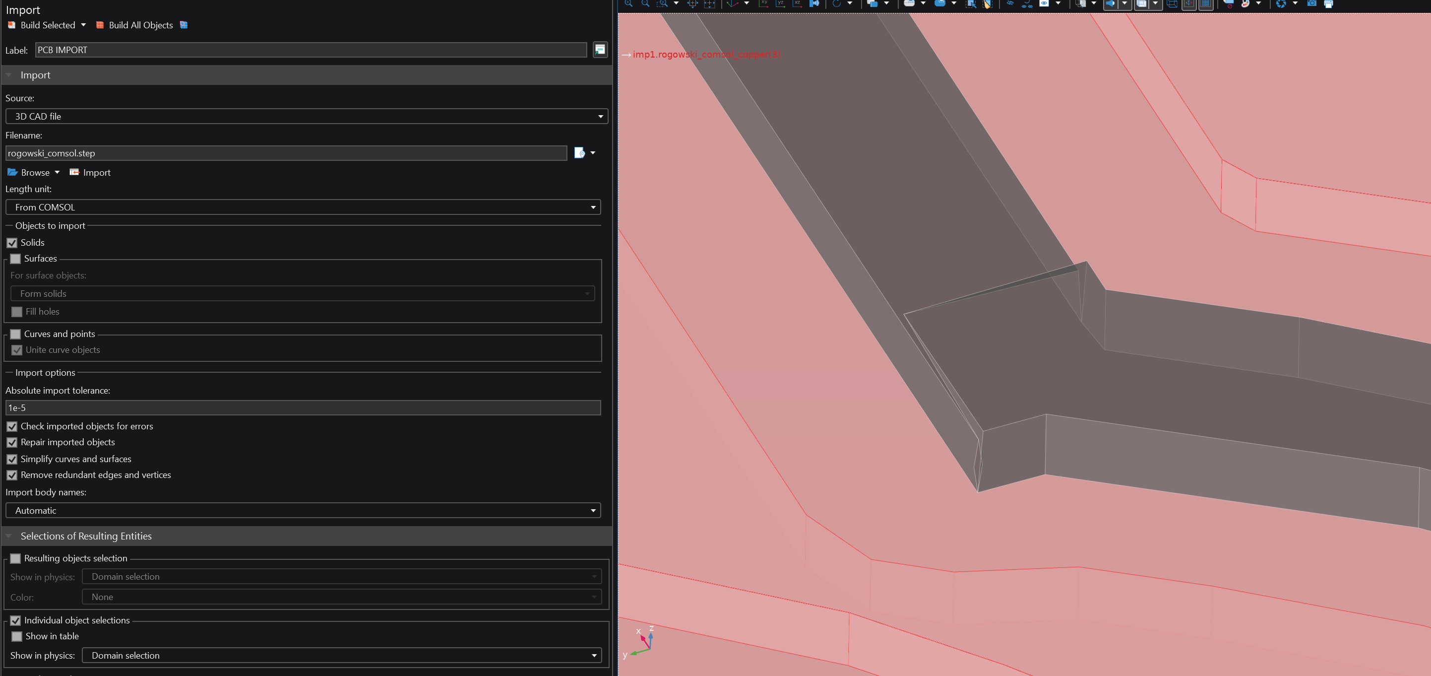
With the default STEP import precision setting being 10 microns, the COMSOL STEP import module produces this mess, which is easy to miss since the feature is so tiny and there are no warnings to suggest that anything is amiss:
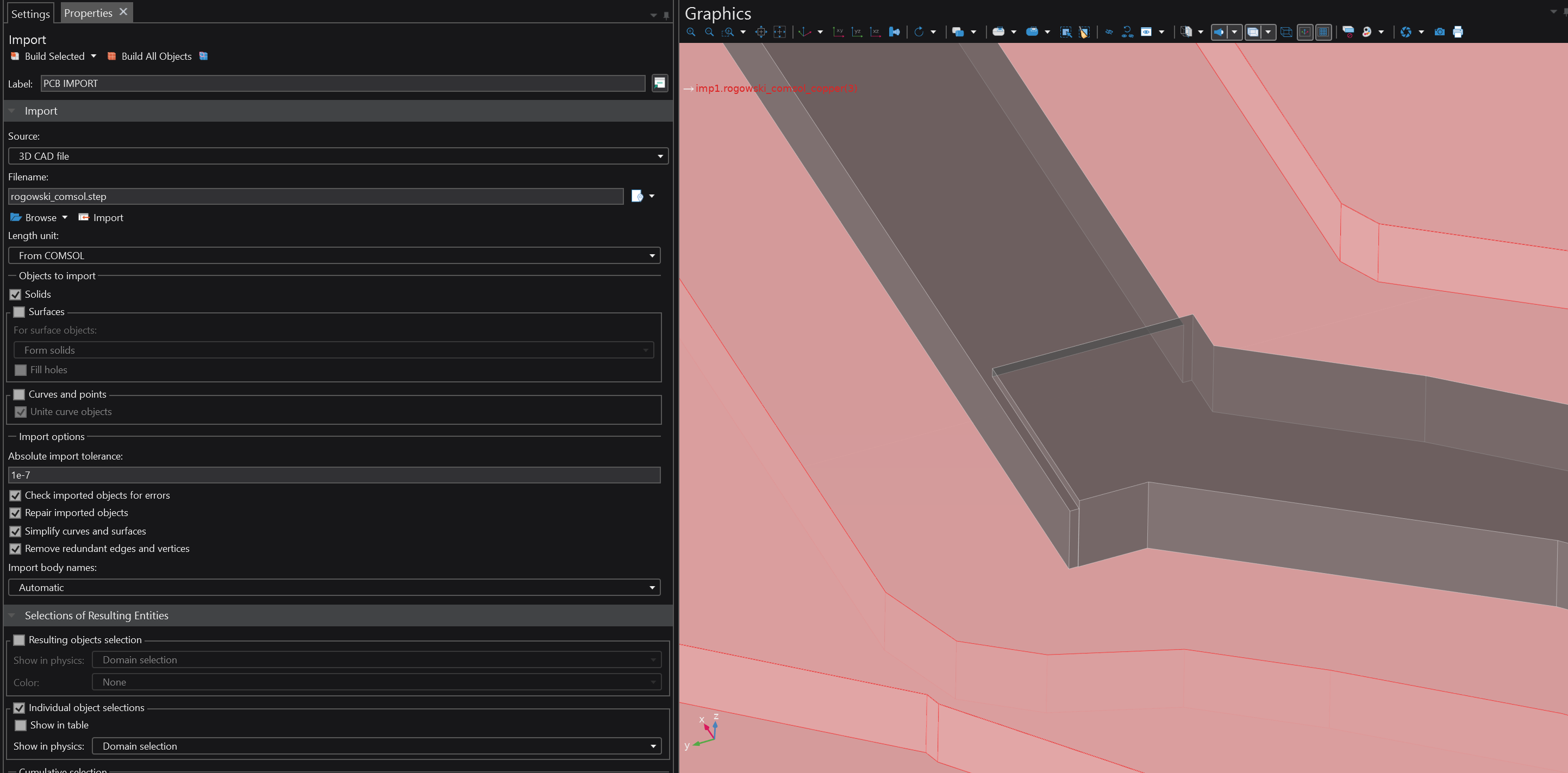
Notably, the Defeaturing and Repair nodes appear to be ineffective against this geometry defect, but refining the absolute import tolerance to 0.1 microns (1e-7 m) restores the original geometry (below). Which is an improvement, but is still not enough to obtain a sensible mesh, since the original features are still too small and the model contains a large number of slivers and small edges elsewhere.
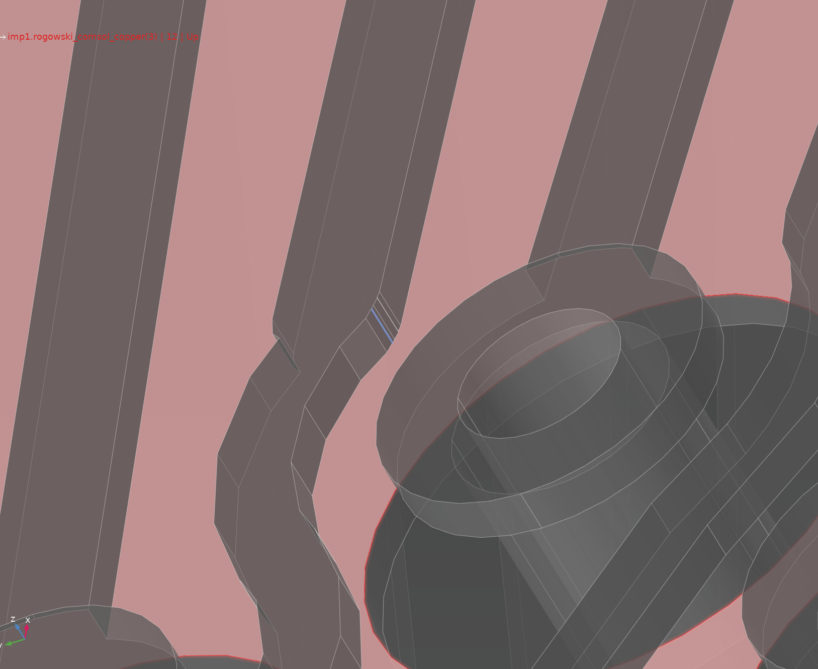
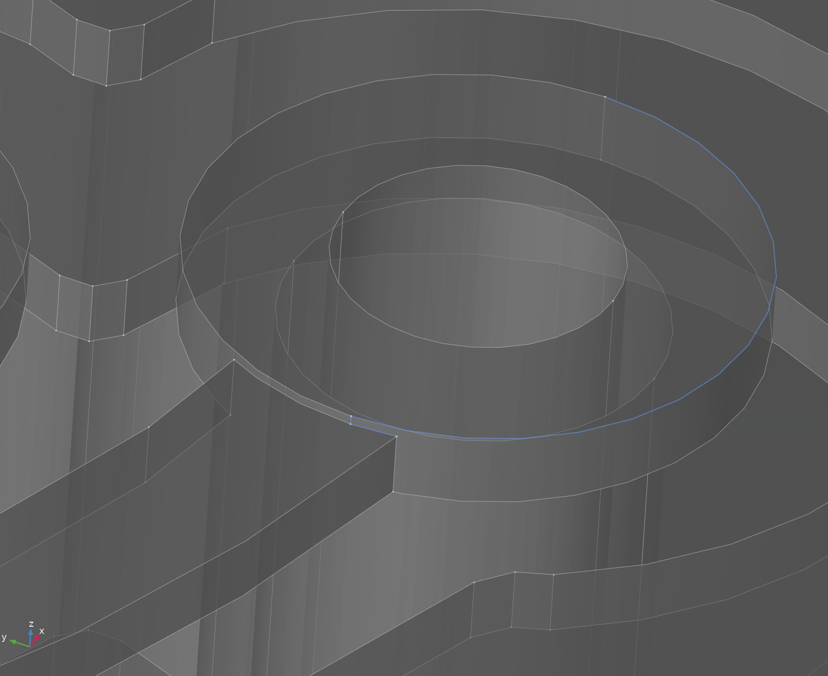
Examples of the remaining issues (notice the highlighted features):
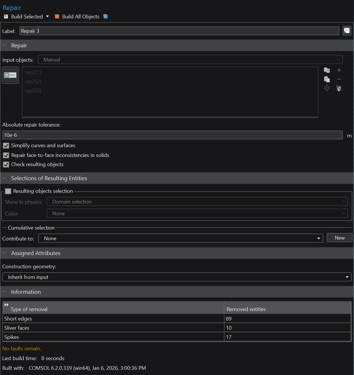
Merely slapping a Delete Spikes / Delete Sliver Faces / etc does not work for an unclear reason – all we get is a generic error message saying that a selected feature could not be removed. Sigh. Nor does a Repair node help by itself; however — per the recommendations given by COMSOL — a sequence of Repair nodes with progressively coarser tolerances appears to do the trick. Having a sequence of three repairs like this, going from 1 micron to 5 to 10 microns, appears to produce a mostly well-formed model:
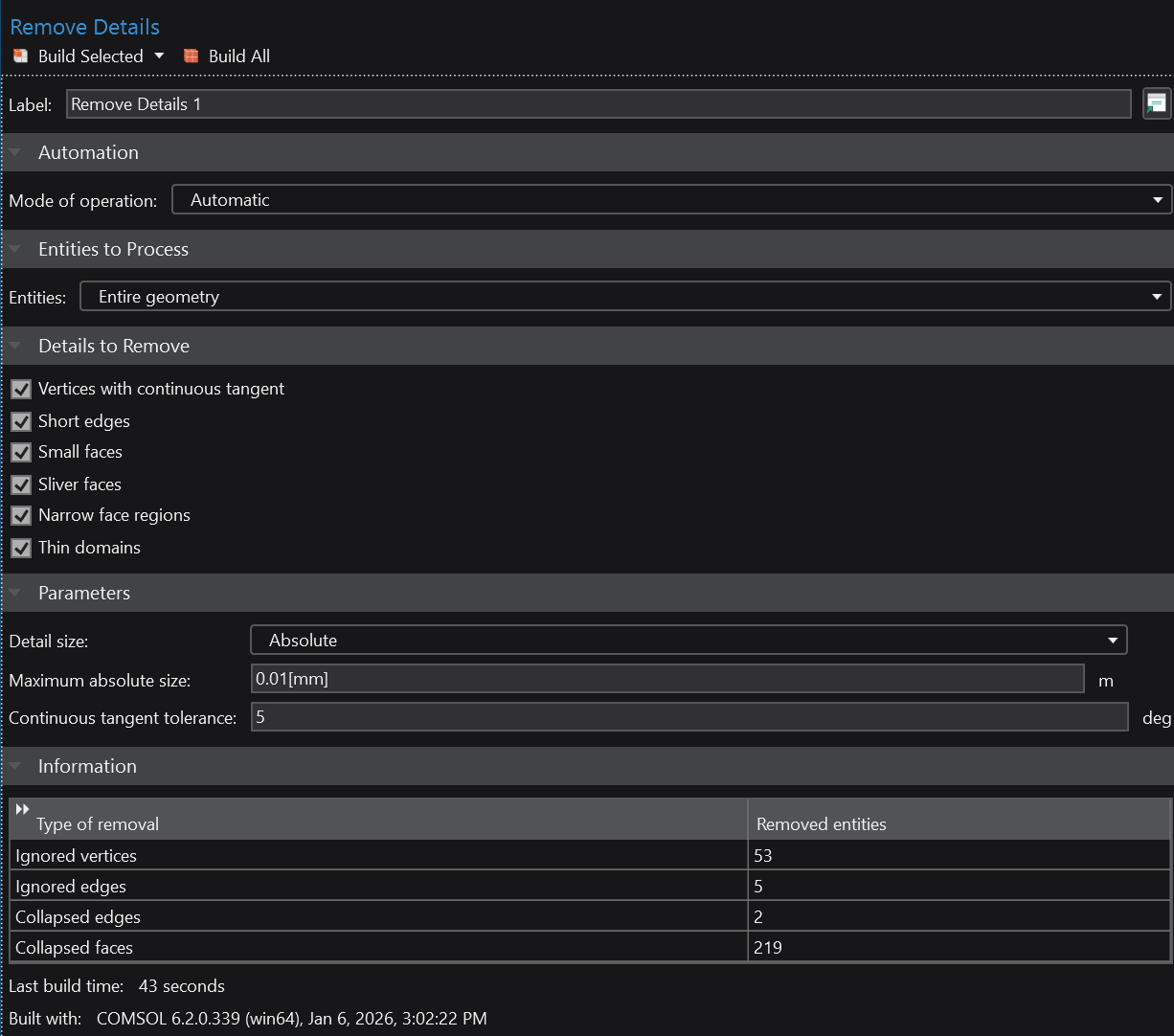
To polish off the remaining imperfections, we slap a couple of Remove Details on top with the absolute tolerance set to 10 and 15 microns, as shown below. It is critical that the tolerance is set manually because automatic selection will collapse valid model features and subsequently fail with an internal COMSOL assertion failure.
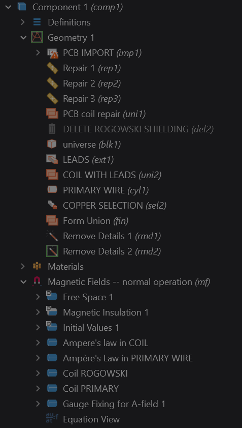
This results in a much cleaner model that can be meshed successfully without warnings and solved using under 200 GiB of RAM (note: A-field gauge fixing had to be disabled for the simulation to work). The resulting model builder tree looks as follows, next to the final mesh with 7.5 million elements: